8 Common ESS System Problems: Causes, Consequences, and Prevention
Over the years, as both a manufacturer and a system integrator, we’ve supplied battery systems to a wide range of markets — residential ESS across Southeast Asia and Africa, commercial ESS across the U.S. and Europe — and run a fair number of post-sales troubleshooting sessions along the way: online, mostly software-related, and on-site, mostly mechanical faults with a range of underlying causes.
Most of what we see in the field doesn’t trace back to a product defect. It traces back to a collection of installation-handling issues, and sometimes to the sheer complexity of the ESS itself, which has to integrate with equipment well outside the battery — diesel generators, EV chargers, payment systems, energy management platforms. Much of that surrounding equipment comes from different players across the globe and is still maturing, which makes a fully thorough installation and commissioning genuinely difficult, especially on commercial and industrial projects. That’s not an excuse — it’s an observation. Many of these faults are preventable. The eight ESS system problems below are the ones we see most often: what causes them, what they lead to, and what prevents them.
1. Poor Operating Conditions
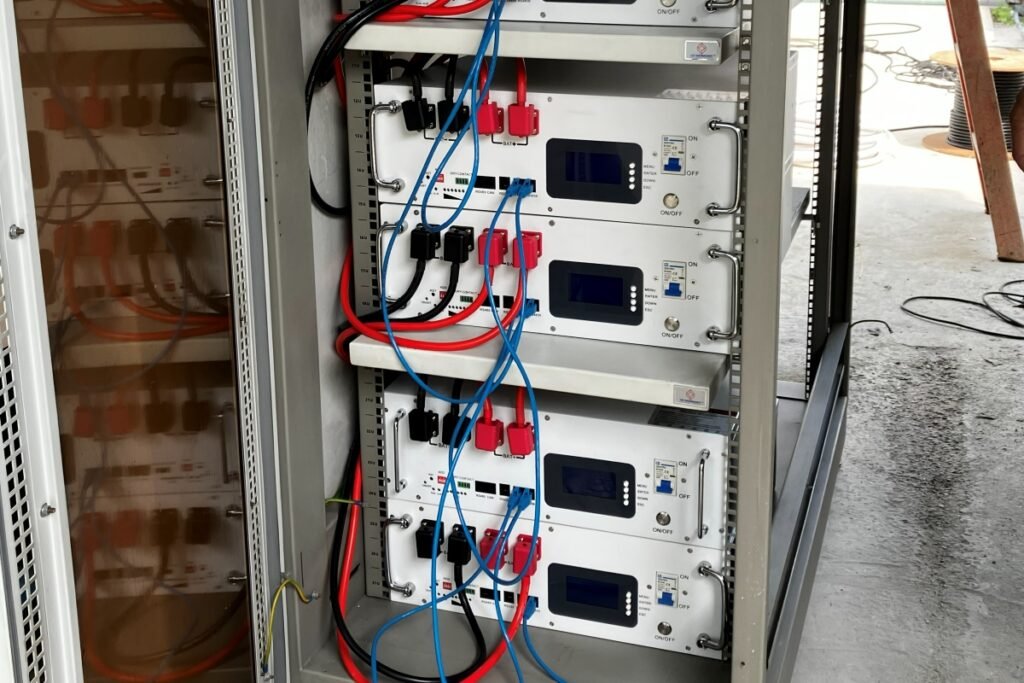
An ESS is only as good as the environment it’s installed in. On site, we commonly see batteries installed inside a rack cabinet — a reasonable choice, since batteries are always installed in some form of shelter to begin with. A cabinet with enough vent holes, a powered DC fan, or open side and back covers is generally fine; most residential ESS units don’t even need a dedicated cooling fan. The problem shows up specifically with a closed or sealed cabinet that lacks sufficient airflow — that combination, or ambient temperature consistently outside the optimum range, is what creates real heat-dissipation issues. Blocked air inlets or outlets, failed or under-specified cooling fans, and direct sunlight compound the same problem.
We’ve also seen installations where cabling wasn’t run through conduit, leaving it exposed to damage that’s easy to dismiss until it happens — wiring chewed by rodents being one case we’ve encountered on site.
Potential consequences: elevated operating temperatures, reduced battery performance and lifespan, and thermal protection alarms that interrupt normal operation.
Prevention: size the enclosure and ventilation for the battery’s actual heat output, keep air inlets and outlets clear, and avoid direct sun or unventilated cabinets — especially in hot, humid climates where ambient temperature is already working against the system before any load is applied. Route cabling through conduit rather than leaving it exposed, both for physical protection and against pest damage.
2. Reversed Polarity and Incorrect Electrical Connections

Reversed positive and negative connections during battery installation are a basic error, but a costly one. The same goes for incorrect wiring between battery packs, between the battery and inverter, or between other system components — and for energizing a system without first verifying polarity and voltage.
We’ve seen this happen in practice: a battery’s positive and negative terminals were reversed during installation, causing a rapid rise in cell temperature that immediately damaged that module’s master control board — the BMS board itself. Because the modules were interconnected, the fault didn’t stay contained: the rest of the battery modules were affected too, and recovery required reconfiguring the control boards and re-running cell balancing across all affected modules, not just replacing the one damaged board.
Potential consequences: damage to the BMS, inverter, contactors, or other electrical components, and in severe cases, further cascading damage and safety hazards.
Prevention: verify polarity and voltage with a meter before every connection, use polarized or keyed connectors where available, and follow a documented commissioning checklist rather than relying on memory or color-coding alone.
3. Improper Installation and Loose Electrical Connections
Insufficient tightening torque on battery terminals, cable lugs, and connecting screws is a small oversight with outsized consequences. So is incorrect cable sizing, poor crimping, or unsuitable cable terminals — and loose connections between battery packs or between the battery system and inverter, however they occur.
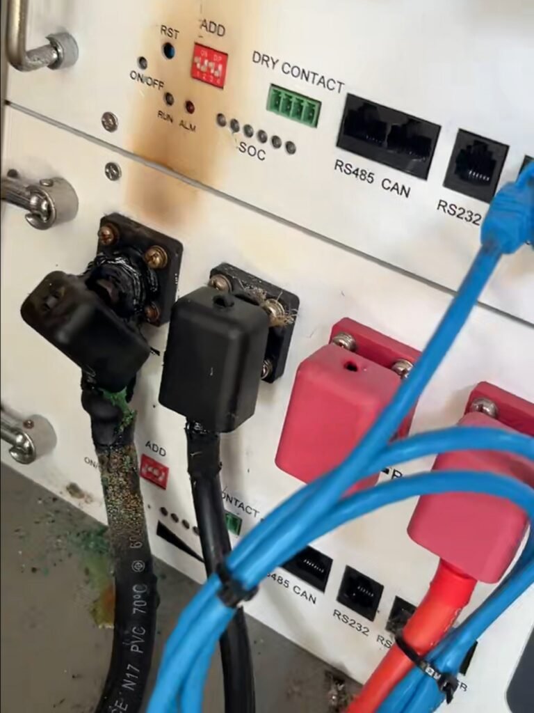
One real-world case illustrates why this matters: the main DC cable between the last battery pack and the inverter burned. Tracing it back, we found the root cause at the cable terminal itself — it hadn’t been tightened sufficiently — and in a related case, the screw securing the cable terminal to the battery terminal had simply loosened over time. The mechanism is simple but easy to underestimate: a loose connection creates high contact resistance at the joint, which generates localized heating under load, and left uncorrected, that heating leads to arcing and eventual cable or terminal failure. Fortunately, in both cases the damage stayed contained to the terminals and cables — the BMS board and battery cells remained intact.
Prevention: follow the specified tightening torque, use appropriate tools and cable accessories, and inspect connections before commissioning rather than assuming an installation was done correctly because it powers on.
4. Improper Earthing and Inadequate Electrical Protection
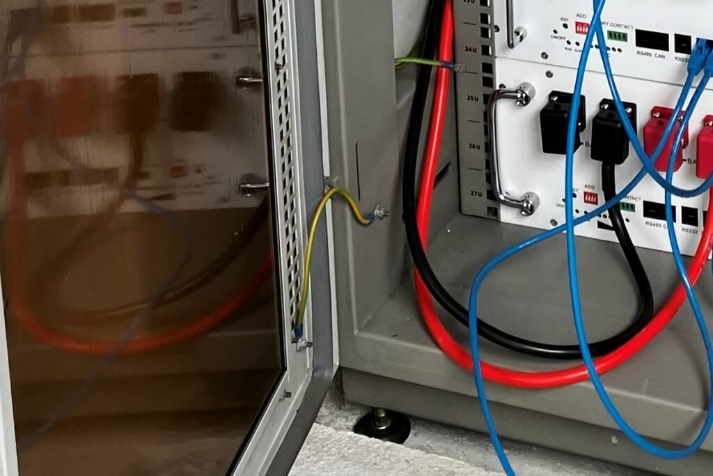
Missing or inadequate protective earthing and bonding is a serious gap when it occurs — but in most cases, earthing isn’t actually where problems originate; it’s a well-understood requirement and installers generally get it right. The issues we’ve seen are more specific. Certain commercial ESS cabinets require earthing routed exactly as stipulated in the product’s installation guide — departing from it, even with a technically reasonable alternative, can disrupt communication between system components. In another case, electromagnetic interference from nearby equipment disrupted successful commissioning entirely, despite the earthing and protection setup itself being correct.
Potential consequences: increased electric-shock risk, ineffective fault protection, damage to electrical components during a fault, and — in the routing- and interference-related cases above — communication disruption or failed commissioning without any conventional electrical fault.
Prevention: verify earthing continuity and bonding against the manufacturer’s requirements and applicable codes as a distinct commissioning step. On commercial cabinets, follow the specified earthing routing exactly rather than substituting an equivalent-looking alternative, and account for electromagnetic interference from nearby equipment during commissioning, not after.
5. Incorrect BMS Settings and Battery–Inverter Communication
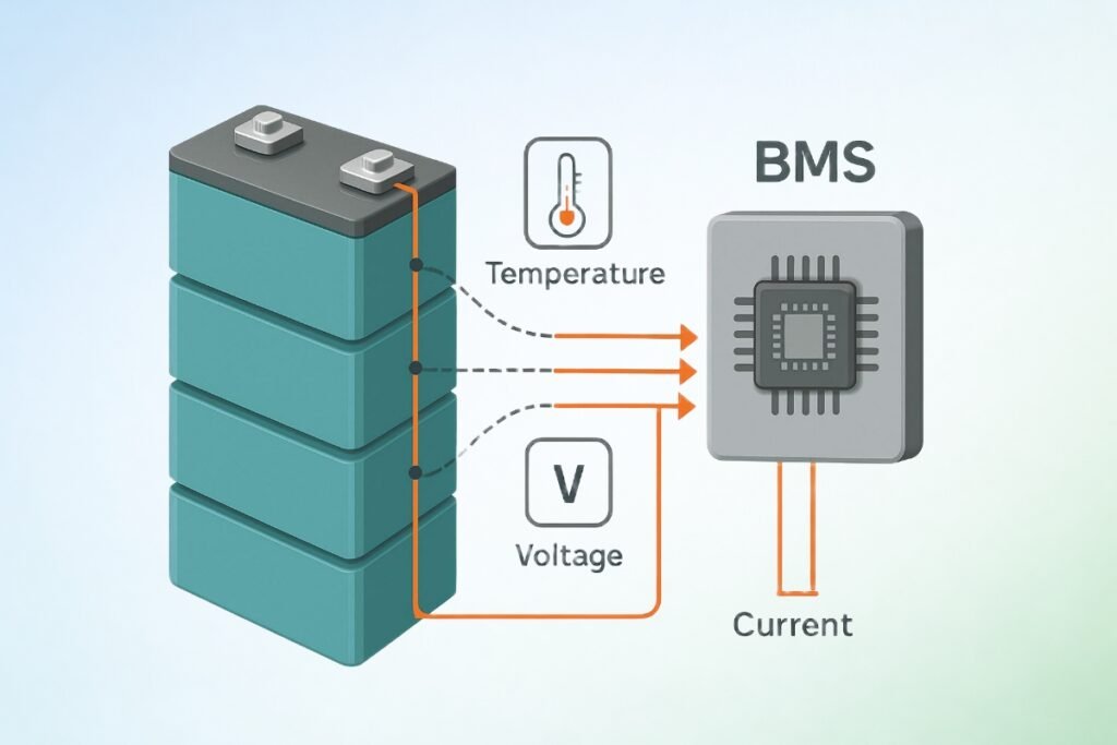
This is where most of our online troubleshooting calls actually land. Incorrect charging and discharging voltage limits, and incorrect maximum charging and discharging current settings, are configuration errors rather than hardware faults — but they produce real operational problems all the same. Getting the communication protocol between the BMS and inverter configured correctly, including CAN or RS485 settings, is a recurring point of friction during commissioning, and we regularly walk installers through it remotely: an incorrect battery type, protocol selection, or communication parameter can stop the system from operating as intended even when every physical connection is correct.
Potential consequences: communication failures, unexpected shutdowns, unnecessary BMS protection events, restricted charging or discharging, and operation outside the battery’s intended limits.
Prevention: provide clear configuration instructions, approved inverter settings, and practical commissioning support for installers, rather than leaving protocol and parameter selection to trial and error in the field.
6. Incorrect Protection Device Selection or Coordination
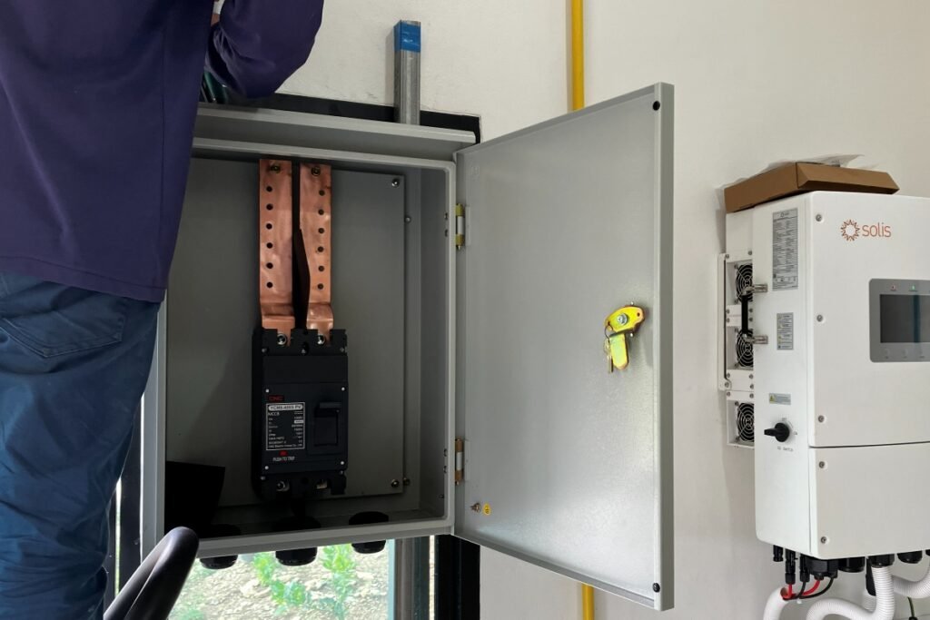
This is one we check closely whenever we review a commercial system design. Fuses or circuit breakers with unsuitable voltage, current, or interrupting ratings are a frequent finding, as is protection that’s undersized for the actual DC cables and battery branches. Protection devices that are incorrectly installed, or simply unable to interrupt the available fault current safely, can leave a system looking protected on paper while offering little real protection in practice.
Potential consequences: failure to isolate a fault effectively, damage to cables and components, and increased fire risk when a fault isn’t cleared the way the protection scheme assumed it would be.
Prevention: select and coordinate protection devices — fuses, circuit breakers, and disconnect switches alike — according to the battery system design and the manufacturer’s specifications, confirming interrupting capacity against the actual available fault current rather than against a generic rating.
7. Insufficient Monitoring and Maintenance
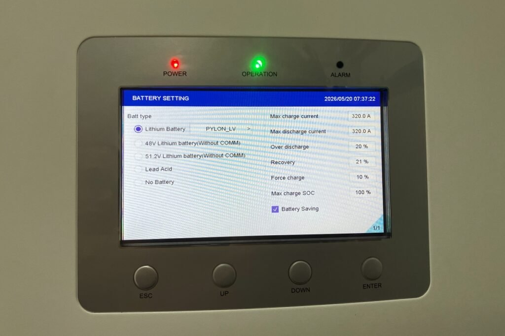
We see this play out differently depending on who’s actually watching the system, and it’s worth treating residential and commercial separately.
Residential ESS: end users often don’t understand BMS alarms or know how to interpret system warnings, and alarms can go unnoticed if they don’t regularly check the inverter display or monitoring app. Installers, for their part, may not continuously monitor system status remotely or conduct regular on-site inspections after commissioning. What we tend to see is a minor fault sitting unresolved until the system shuts down, loses performance, or fails more seriously.
Commercial ESS: dedicated personnel and monitoring platforms are more common at this scale, but we’ve found monitoring alone doesn’t guarantee faults get resolved promptly. Alarm escalation, response responsibilities, inspection schedules, and preventive maintenance all need defining in advance — regular on-site checks should supplement remote monitoring, not replace it.
Prevention: establish clear responsibilities between the manufacturer, distributor, installer, and end user; provide practical alarm-handling instructions and maintenance guidelines; and, where appropriate, arrange remote monitoring, alarm notifications, and scheduled inspections rather than leaving fault detection to chance.
8. Inadequate Cable and System Design for Actual Operating Conditions
Unlike loose or poorly terminated connections — an installation-execution problem, covered above — this is a design-stage problem we catch earlier, during system design review: the cable, or the broader system design around it, was never sized correctly for how the system actually operates. A cable can be installed perfectly and still be the wrong cable.
What we typically find is cable sizing or connection arrangements that don’t account for actual continuous current, peak current, cable length, or installation conditions, along with battery and inverter operating limits that weren’t adequately considered at the design stage. Under sustained high loads, the result is excessive voltage drop or localized heating — not because anything was installed badly, but because the design never matched the load the system would actually see.
Potential consequences: poor system performance, unexpected protection events, overheating, and premature component failure.
Prevention: verify the design against the actual load profile, cable installation conditions, and the specified continuous and peak operating limits — ideally before procurement, not after a problem shows up in the field.
Final Thought
None of these eight ESS system problems are exotic — we see them repeat across markets, system sizes, and installer experience levels, and that’s precisely why they’re worth writing down. Each one is well understood and preventable with the right checks at the right stage: design, installation, commissioning, or ongoing operation. What tends to separate a reliable ESS installation from a troubled one, in our experience, isn’t luck. It’s whether those checks actually happen — and whether the manufacturer, installer, and end user all know whose job it is to make sure they do.